Project 7 Part 1: Image Warping and Mosaics
Alan Yao
Description
Image alignment and stitching algorithms and techniques are quite common. They're found in daily use in cell phones, digital cameras, video cameras, et cetera. Notably, given two images of the same scene, if the two images were taken from a similar location (or the images are of a far-away or planar scene), we can reconstruct the full scene by applying a camera transformation onto one image to warp it into the space of the other image.
More concretely, we can compute the projective transformation matrix H on homogenous coordinates in the canonical camera coordinate space. That is, we transform image coordinates x in [0, xmax] and y in [0, ymax] to [-1, -1] and [-a, -a], where a is the aspect ratio. Then we take the homogenous coordinates, where the image is at distance 1 from the camera, and compute a full 8-dof 2D perspective transformation (keeping the scaling parameter constant). This is done by hand-selecting, or in this project, automatically finding matching corner points. At least 4 will be required to specify a homography.
Finally, we'll explore some additional techniques to produce better images, and take advantage of projective transformations.
Image Rectification
Given some single-image view, we can change the viewing angle of the image by specifying control points within the image and then specifying where they should be in the resulting image. This gives a homography, which when applied, makes it seem like the viewing angle has changed.
However, this is greatly limited since we only have access to imw*imh rays of information, essentially; interpolation aside, we have no additional information about the geometry of the image. This means by doing a viewing transform, we are essentially remapping texture angles on a plane. But while we cannot view things we previously have no information on, this can still generate a useful result.
| Original Image | Rectified Image |
|---|---|
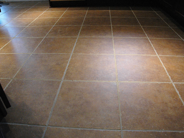 |
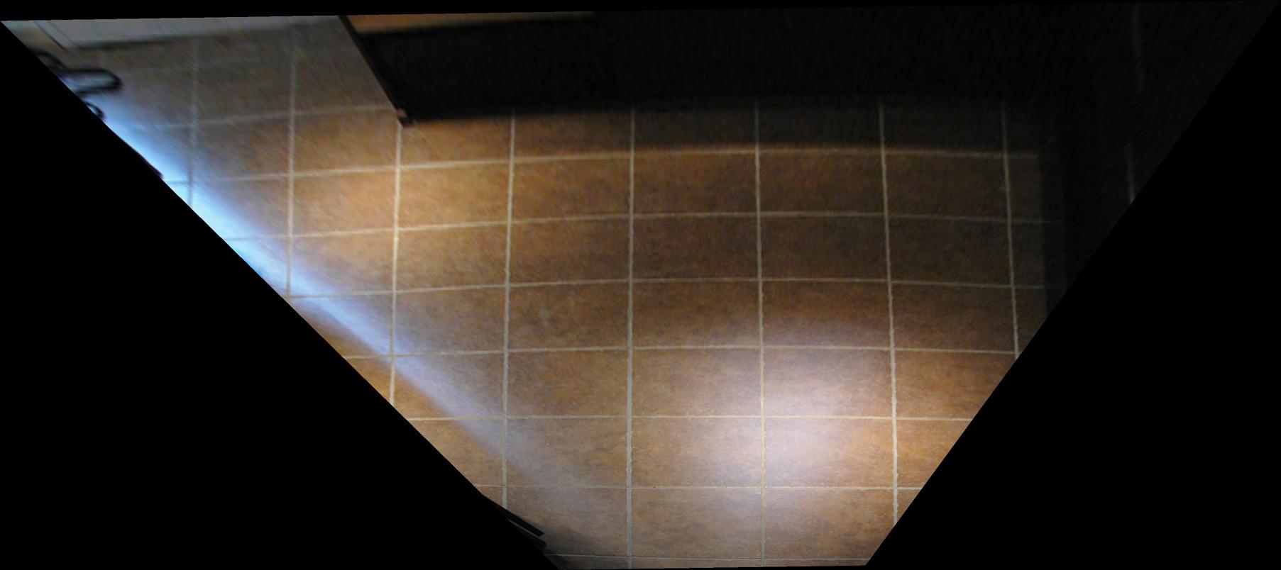 |
 |
 |
| For the above two images, I select a tile and an arbitrary rectangle (specified manually). Then by computing the homography and applying it, we see the viewpoint looking directly at the tile. |
|
 |
 |
|
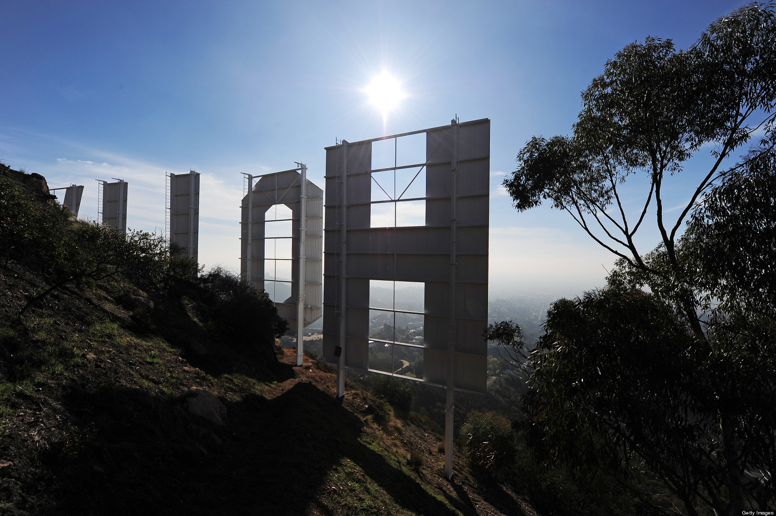
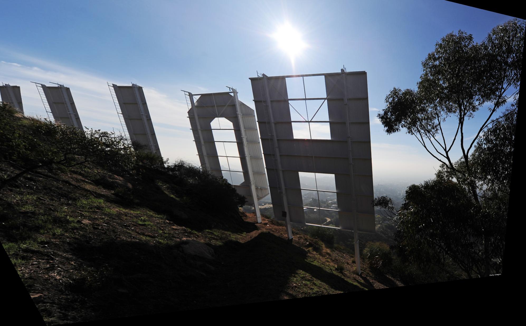
For the hollywood sign, I select a square in the sign and transform it to some arbitrary parallelogram. This has the effect of shifting the viewpoint downwards. |
|
Mosaic Stitching
For image stitching, we follow the general algorithm:
1. Select, or automatically detect corresponding control points on a pair of images. The more (accurate) correspondences, the better.
2. Compute the homography that satisfies the least-squares solution Ax=b formulated as follows:
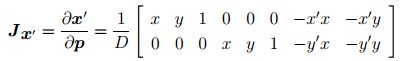
and reshape to obtain H.
3. Forward warp the corners of the image to obtain a bounding box to inverse warp on.
4. Blend the two images as follows: compute the region of overlap. Suppose we are blending two images horizontally; then we replace everything to the left with white and everything to the right with black, and everything within the region with a gradient, and pass this into our laplacian pyramid blending code. I will also demonstrate an example of naive blending.
 |
 |
|
|
| A basic example of a stitch. This was done automatically, using corner detection. | |
 |
 |
|
|
|
|
|
The first stitch is done naively. We simply compute the regions where the warped image is non-zero and use that as a mask. The second stitch has a mask as described above, and uses laplacian pyramid blending. Notice how all edge artifacts are gone. This stitch was also done automatically. Notice the slight distortion along the right edge. This is due to changing focal lengths and radial lens distortion. This will be addressed (and fixed) in a later section. |
|
 |
|
|
|
|
My best stitching result. These images were taken at Point Montara Lighthouse, on a stable surface. This results in very stable transformations with little to no distortion. This was actually my first test, so points were selected manually. |
|
Bells & Whistles : Spherical Map
We can re-transform our image to fit the spherical lens used; this allows for vertical stitching without distortion if we can moderately closely guess the focal length. In canonical camera coordinates, we apply the transformation:
And then perform a forward warp to retrieve the spherically warped image. This allows for both vertical and horizontal stitching without distortion, if we guess an approximately correct focal length.
|
|
|
|
|
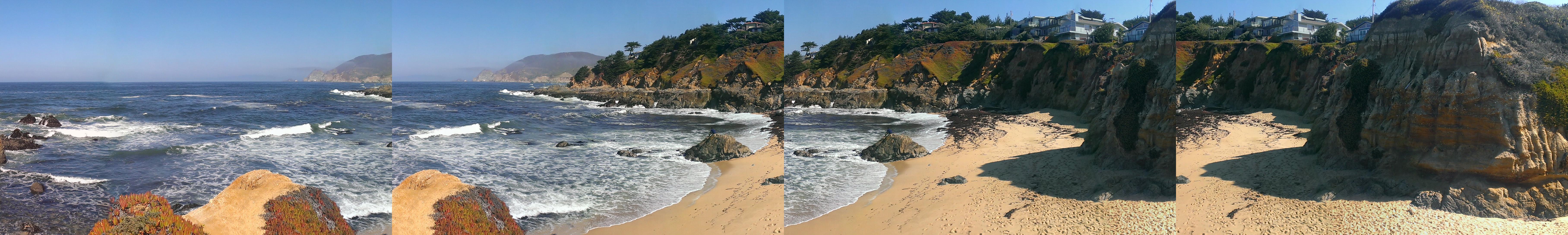
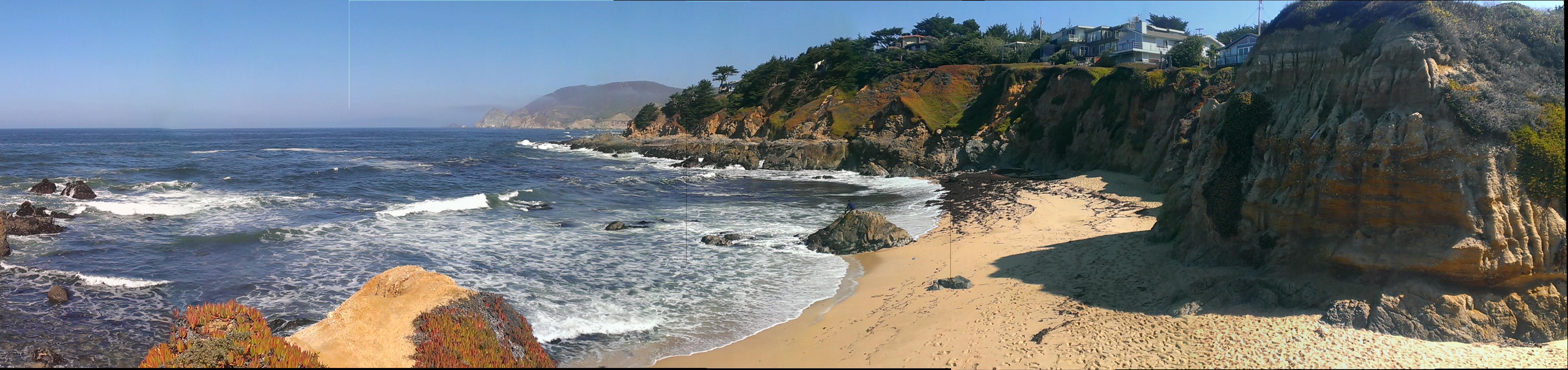
First we warp each image to its spherical projection. Then, on the left we have the spherically-projected stitch, and on the right we see a basic, non-projected stitch for comparison. |
|
Bells & Whistles : Cylindrical 180+ degree shot
A major problem with directly applying homographies is that it does not take into account radial distortion, especially around the edges. This can be resolved by first performing a cylindrical transformation before stitching. However, this does require knowledge of the focal length to create an accurate reproduction, and to allow for translation-only stitching.
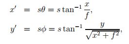
Similarily to the spherical warping, we first apply a forward warp using the coordinate system:
and use matlab's griddata to interpolate values. Note that this must be done in the canonical camera coordinate space (otherwise you will only have a quarter of a cylinder). Then we align the images, allowing for 180+ degree mosaics.
 |
|
 |
|
|
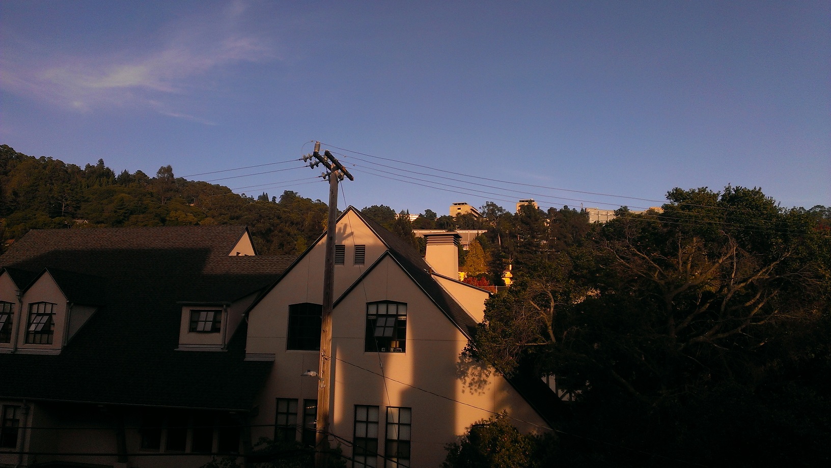
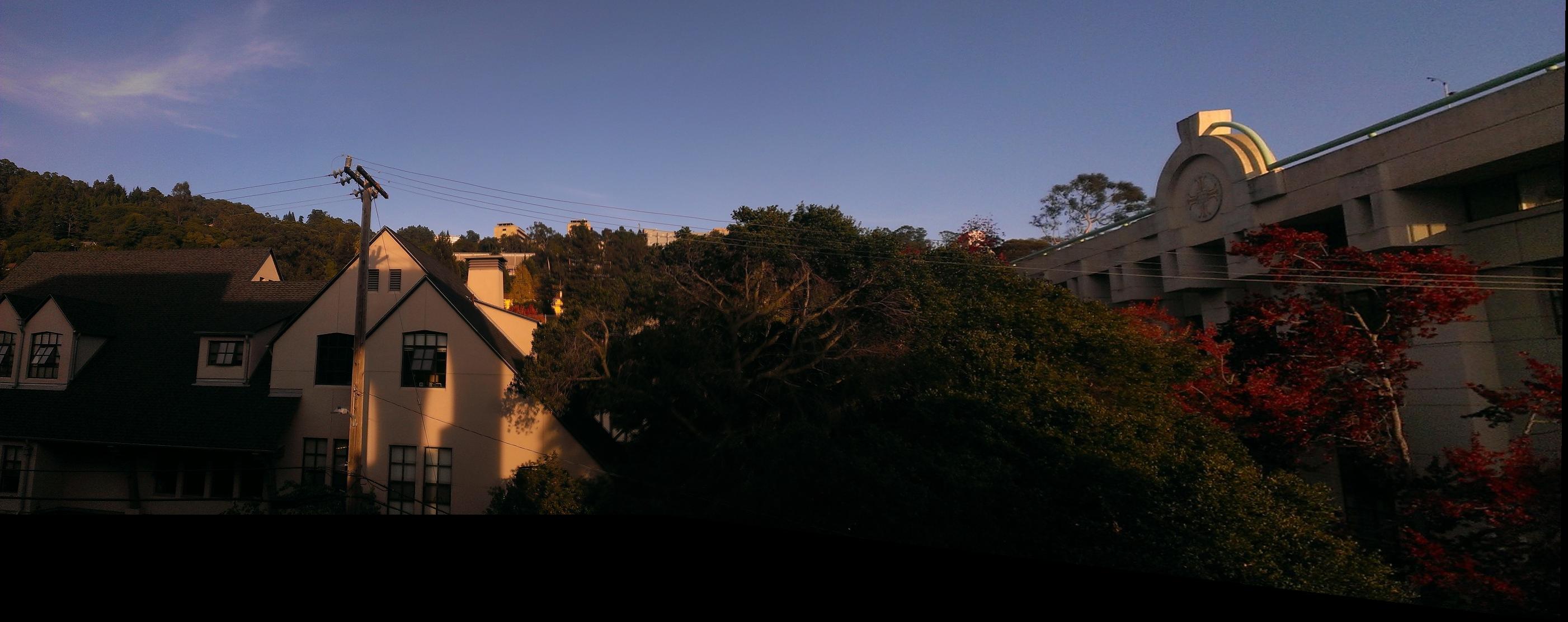
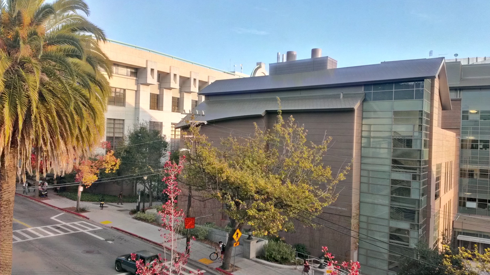
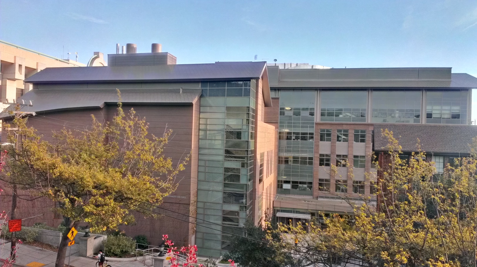
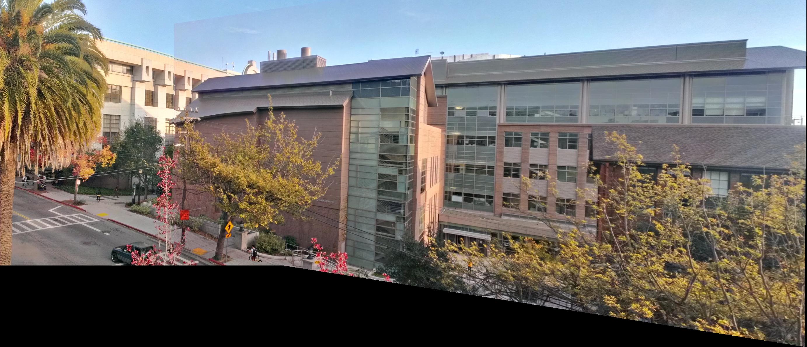
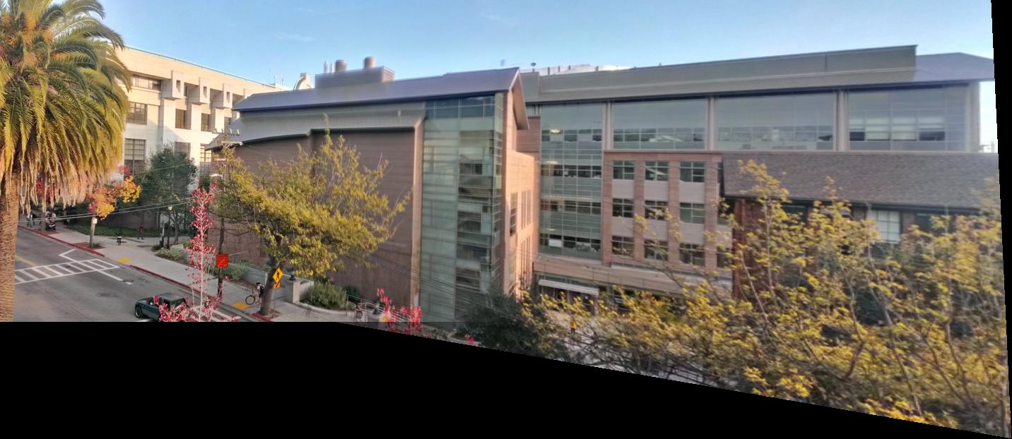
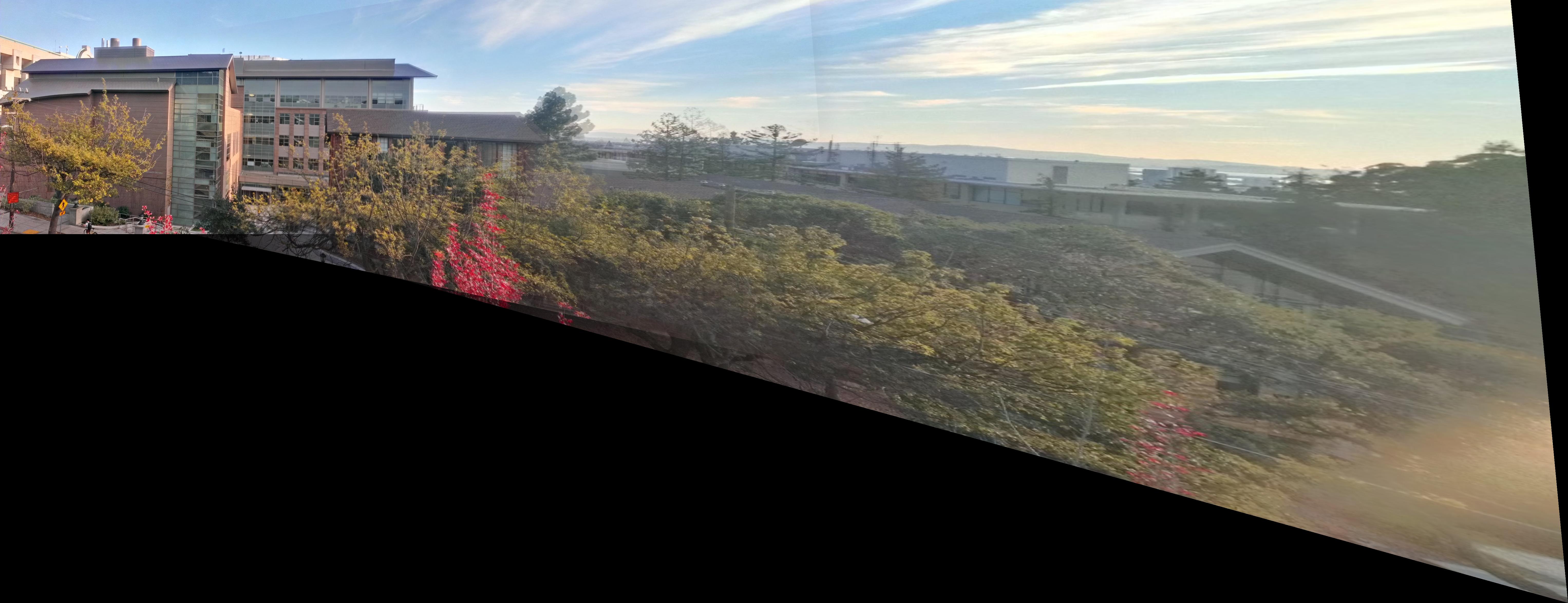
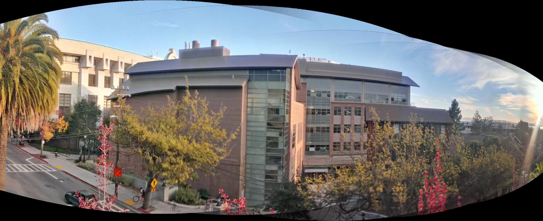
First, we show a result on stitching images using only homographies. This is the result of stitching four images together; we notice the cascading distortion effects, as the image gets stretched more and more. This is avoided mostly by performing a cylindrical warp, as demonstrated in the second mosaic, which spans a full 180 degrees as taken from the 6th floor Soda balcony. However, this is not a perfect cylindrical warp. This is mostly the fault of taking the pictures using a cell phone camera on a non-stable surface. Not only does the focal length change from picture to picture due to an autofocus "feature" that I can't control, it's really, really hard to keep the camera rotationally still. Even through this, the result is much better than the standard stitching. |
|
Bells & Whistles : Image Insertion
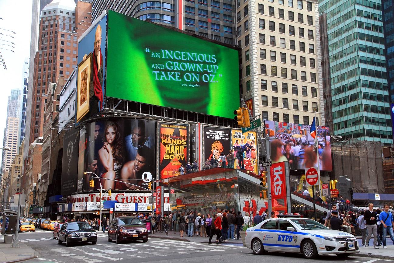
Given some image, we can also insert it into another image using a homography to ensure that the insertion lines up correctly with the target area. Below I demonstrate two examples on times square.
 |
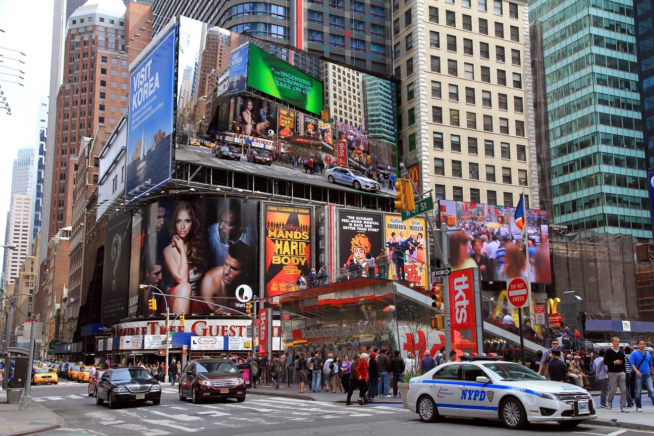 |
| I didn't know Professor Efros was advertising on Times Square! And wow, times square advertizes itself! |
Bells & Whistles : Automatic Image Alignment
Following the given process, we can also stitch our images automatically. I use this for most of the images in this project (since it's a major pain to actually select control points by hand).
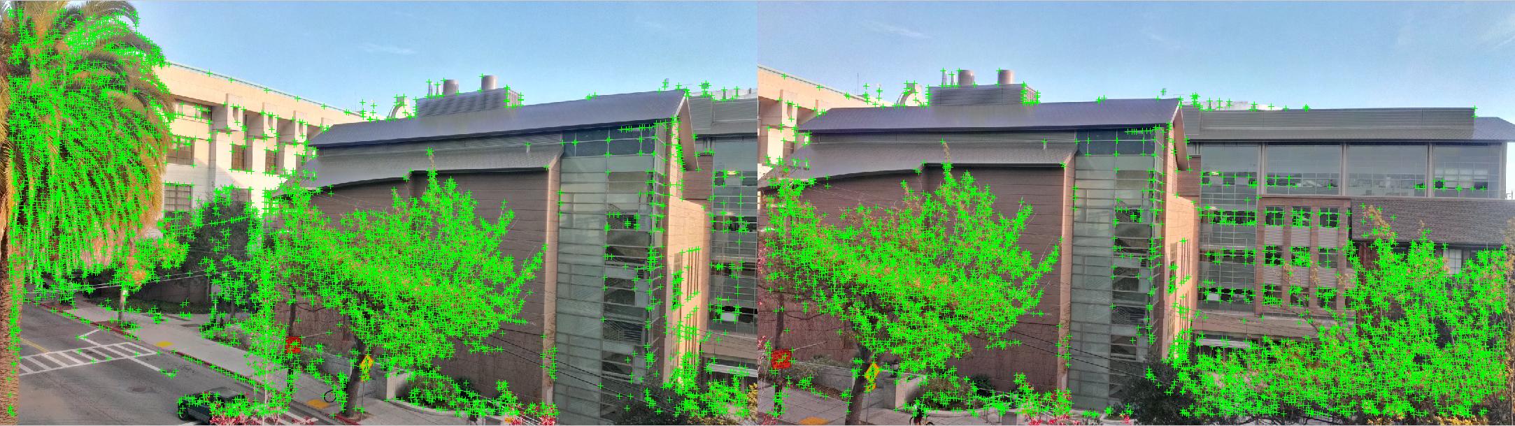
1. Find the Harris detector corner points. This can be done either by convolving with the Harris matrix or using a built-in library (faster).
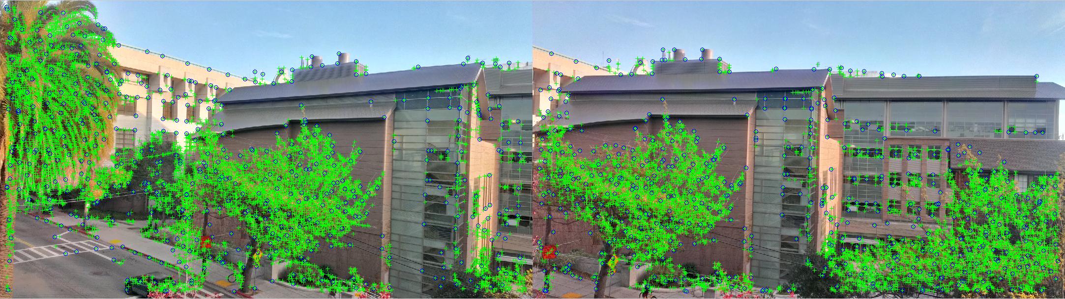
2. Use Adaptive Non-Maximal Suppression to get a well-distributed set of interest points. The output points from ANMS are circled in blue. I arbitrarily chose to find the 500 strongest points. This is done by computing the suppression radius (the minimum absolute distance from p1 where a point p2 exists that has a stronger value) for each point, then sorting.
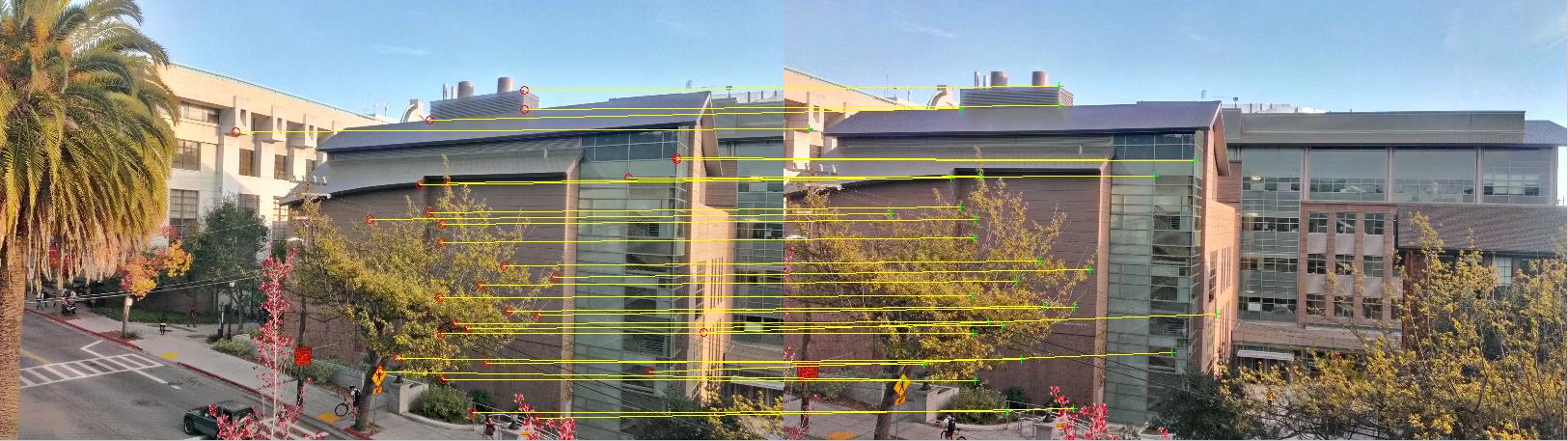
3/4. Extract features as a 9x9 patch around each interest point, after gaussian blurring and downsizing by a factor of 4. Then match features by SSD, threshholding on the ratio between the nearest neighbor and the second-nearest neighbor. Take the 30 strongest matches.
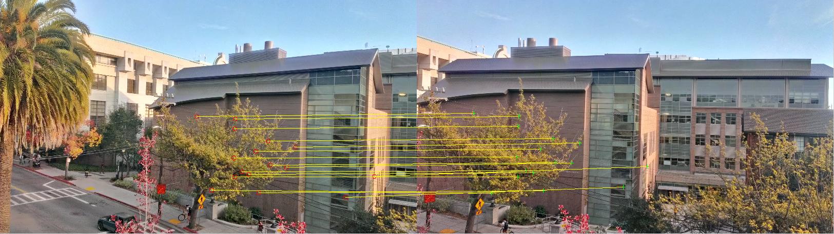
5. Using RANSAC, find a set of matching inlier points by going through multiple iterations. Essentially, we select 4 random points, compute H, and find the number of points that are within 1 pixel of where they should be after transformation; this is the inlier set. Then over multiple iterations, we maximize the size of the inlier set, and use that set to compute the least-squares approximation of H to use for projective warping.
6. Warp and stitch the images together as shown above.
What I learned
Projective transforms are a fundamental part of computer graphics, and of course would play an equally fundamental role in CV. There's still a wide range of applications to explore for the following parts of this project.